July 22, 2019 feature
Seeing smaller through cells: A natural single-cell biomagnifier for subwavelength imaging
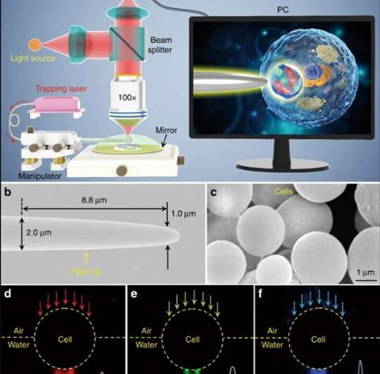
Optical microscopes and tweezers can image and manipulate objects at the microscale for applications in cellular and molecular biology. The optical resolution is, however, hampered by the diffraction limit and therefore both microscopes and tweezers are unable to image and manipulate nano-objects directly. Emerging techniques in plasmonic/photonic nanoscopes and nanotweezers aim to achieve nanometer-scale resolution, although high-index material structures can easily cause mechanical and photothermal damage to the nanoscale biospecimens.
In a recent study now published on Light: Science & Applications, Yuchao Li and colleagues at the Institute of Nanophotonics in China, developed an optical microscope system using living cells as tiny lenses to image and manipulate objects smaller than the wavelength of light. They showed sub-diffraction-limit imaging and manipulation of nano-objects with a non-invasive device, which they constructed by trapping a cell on a fiber tip. The trapped cell formed a biomagnifier that could magnify nanostructures with a resolution of 100 nm, under white light microscopy. Using the biomagnifier, Li et al. formed a nano-optical trap to precisely manipulate an individual nanoparticle with a 50 nm radius. The technique provides a high-precision tool for optical imaging, sensing and assembly of bio-nanomaterials without mechanical or photothermal damage.
Optical imaging to manipulate small objects is crucial for medical diagnosis, biological sensing, cellular exploration, molecular training and materials assembly. Tweezers and microscopes are standard devices for noncontact imaging and manipulation of minute samples ranging from a few nanometers to several microns. Nevertheless, it is challenging to use the technology to image at the nanoscale, since optical resolution is restricted to approximately half the illumination wavelength.
Scientists have achieved dramatic progress of near-field nanoscopes and nanotweezers in the past few decades to achieve optical imaging at nanometer resolution. These imaging techniques were withheld by high-index inorganic materials such as noble metals and semiconductors used for their fabrication—that can mechanically damage samples of biological cells or tissue during near-field imaging and manipulation.
Scientists therefore investigated simpler optical imaging schemes based on dielectric microspheres to overcome the diffraction limit common to conventional microscopes. While the technique is label-free and feasible, such microspheres are based on artificial inorganic materials such as silicon dioxide (SiO2), titanium dioxide (TiO2) and barium titanate (BaTiO3). Researchers are therefore interested in developing a natural biomaterial to construct a biocompatible device for bioimaging, manipulation and biomagnification at nanoscale spatial resolution.
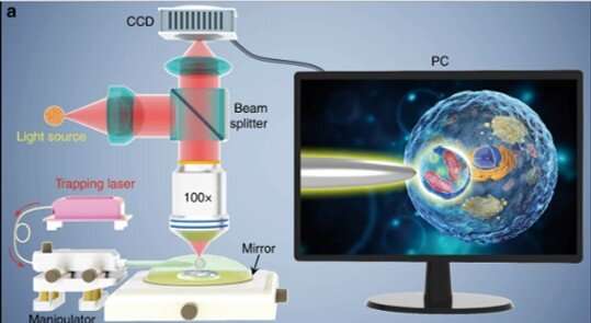
Li et al. selected biological cells to replace microspheres since cells are both abundant and biocompatible in contact with biological systems. For instance, scientists can use living cells to manipulate light in biological environments and act as optofluidic microlenses, optical probes and even incorporate E.coli as biophotonic waveguides. In the present work, Li et al. enhanced the index contrast of living cells by using a spherical shape semi-immersed in a medium to achieve focusing at the sub-wavelength. The scientists captured biological images using the subdiffraction light spot to illuminate targeted samples along with white-light microscopy. The nano-sized light spot exerted a strong optical gradient force to trap and manipulate a single nanoparticle enabling the biomagnifier to also function as an optical nanotweezer.
The scientists conducted all experiments under a reflection-mode optical microscope coupled to a charge-coupled device (CCD) camera and objective lens. They used light sources at 390 nm, 560 nm and 808 nm for excitation, illumination and trapping respectively. Using an optical fiber with a tapered tip, Li et al. trapped the biomagnifier at the end of the fiber, which they controlled by moving the tip using a micromanipulator. Li et al. selected smooth and spherical cells to minimize image aberration and noted the cells to exhibit better focusing performance when semi-immersed in solution to maintain cell viability.
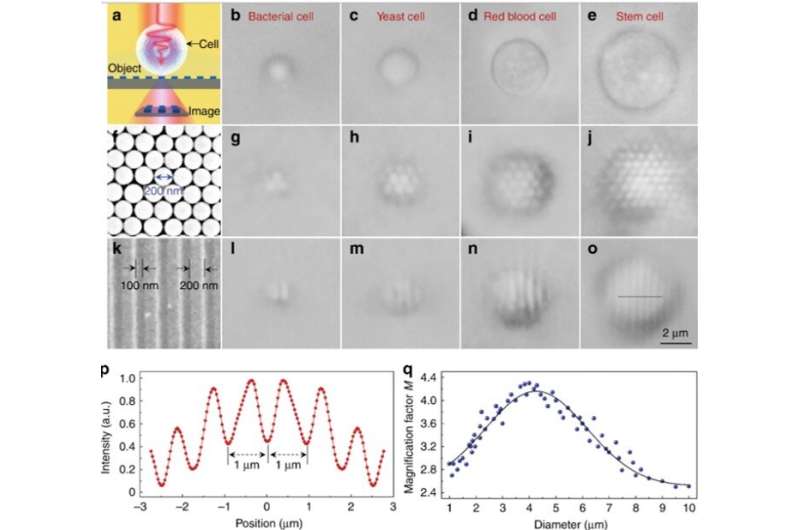
During experimental imaging, the scientists positioned a semi-submerged biomagnifier on top of a test sample and collected the underlying near-field information from the sample, to form a virtual image as detected by an optical microscope. Li et al. prepared a variety of biomagnifiers using diverse cells including bacteria, yeast, red blood cells and stem cells. For the first imaging sample, they used a two-dimensional hexagonal silica nanosphere array with a 200 nm diameter on a glass substrate using a photophoretic technique.
Only nanospheres with biomagnifiers on top of them could be resolved during imaging, whereas nanospheres without biomagnifiers could not be resolved using a conventional microscope. The magnification factor M of the stem-cell based biomagnifiers was determined to be 3.3 times larger (x3.3), and the scientists showed the experimental M depended on the biomagnifier's diameter. Subsequently, Li et al. performed all experiments using biomagnifiers of this diameter.
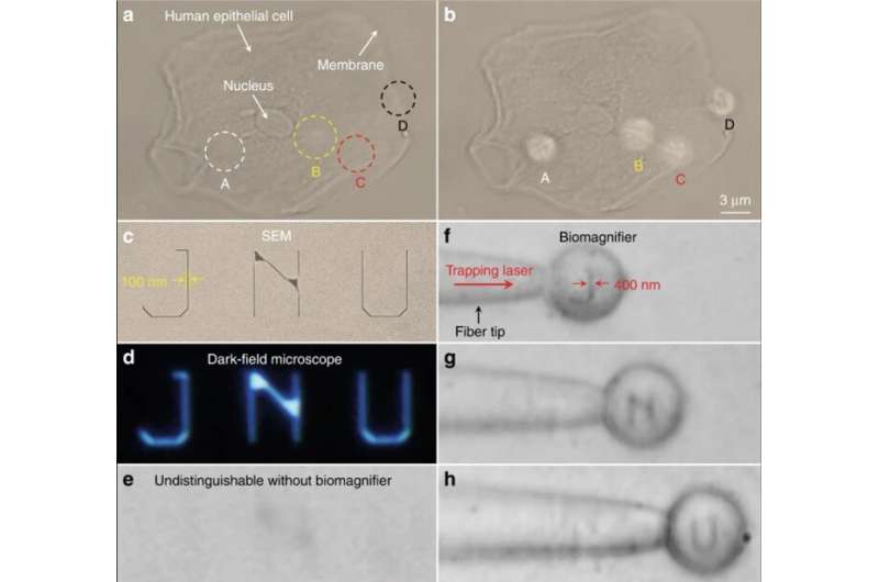
To investigate the applications of biomagnifiers, Li et al. imaged human epithelial cells as imaging targets by growing epithelial cells on a mirror substrate for enhanced light-matter interactions via the interference of the illumination light and reflection light. While it was difficult to distinguish the fibrous cytoskeleton and bilayer structures under a conventional optical microscope, after positioning a biomagnifier on top of the epithelial cells the scientists were able to resolve both structures. To improve the imaging field of view (FOV), they trapped the biomagnifier on a fiber tip and moved it to scan the samples. For example, Li et al. used the setup to scan nanopatterned letters that stood for an acronym of Jinan University—JNU, which they first created on silicon using electron-beam lithography.
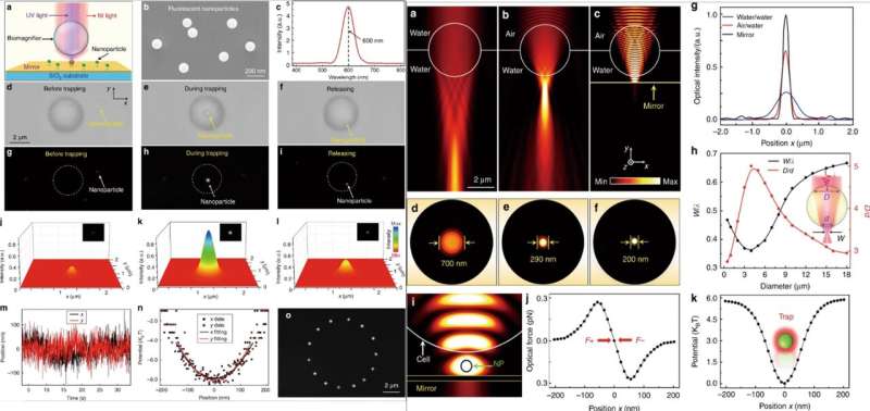
Thereafter, when they simultaneously irradiated near infrared (IR) and UV laser beams on the biomagnifier through an objective lens, they could trap and excite the nanoparticles. For these experiments, the scientists used fluorescent nanoparticles with a 50 nm average radius. When they trapped a single nanoparticle in the focus of a biomagnifier, they observed both optical and fluorescent images of the sample of interest. Li et al. then calculated the trapping stiffness of the particle in real-time using standard optical tweezers. The ability to manipulate a single nanoparticle without contact and precisely via optics will be useful to assemble well-regulated nanostructures. When Li et al. numerically investigated the imaging mechanism and trapping stiffness of biomagnifiers using 3-D simulation and COMSOL software. They observed the subdiffraction-limit light focusing ability resulted from a combined "photonic nanojet" effect and coherent interference enhancement by the mirror.
Limitations of the method included imaging aberration and distortion due to the inhomogeneous intracellular structures of the natural biomagnifier, compared to dielectric microspheres with uniform refractive indices. Fortunately, intracellular materials were optically transparent to visible and near-infrared light and the optical interactions were relatively weak inside a single cell. Intracellular activities could also change the partial refractive index distribution in a cell to cause light distortion during trapping and imaging, but most intracellular activities were ultrafast and did not influence the imaging scheme.
In this way, Yuchao Li and colleagues developed a new experimental imaging technique and verified the experimental capabilities with FEM simulations. Li et al. integrated optical nanoscopes and nanotweezers in a single device to image and manipulate nanostructures simultaneously for the first time in the present work. They promoted the resolution of the technique to 100 nm and proposed a label-free imaging procedure. The scientists envision the living biomagnifier to open new opportunities in super-resolution imaging, real-time sensing and precise nano-assembly of bionanomaterials to form nanoarchitectures of interest.
More information: Yuchao Li et al. Single-cell biomagnifier for optical nanoscopes and nanotweezers, Light: Science & Applications (2019). DOI: 10.1038/s41377-019-0168-4
Hamid Pahlevaninezhad et al. Nano-optic endoscope for high-resolution optical coherence tomography in vivo, Nature Photonics (2018). DOI: 10.1038/s41566-018-0224-2
Bo Huang et al. Breaking the Diffraction Barrier: Super-Resolution Imaging of Cells, Cell (2010). DOI: 10.1016/j.cell.2010.12.002
Journal information: Light: Science & Applications , Cell , Nature Photonics
© 2019 Science X Network


